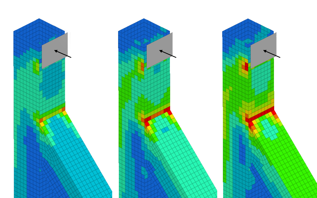
Finite element analysis provides access to a wide range of results, including stresses, strains, displacements, reaction forces and energy histories. However, extracting the maximum value from a contour plot does not necessarily provide the most meaningful measure of structural performance.
Effective interpretation requires an appreciation of the underlying structural mechanics, the modelling assumptions and the engineering question the analysis is intended to answer.
Start with the engineering question
Before interpreting the results, establish what the model needs to demonstrate. Is the assessment concerned with structural strength, stiffness, permanent deformation, fatigue, load-carrying capacity or a specific regulatory requirement?
The appropriate results depend on the assessment criteria. A maximum stress value may be relevant to one assessment, while global deflection, plastic strain, reaction forces or load–displacement behaviour may provide more meaningful evidence for another.
Follow the load and stiffness paths
Understanding how loads are transferred through a structure is fundamental to interpreting FEA results.
In statically indeterminate structures, the distribution of reaction forces depends on the relative stiffness of the available load paths. Components with greater stiffness will generally attract a larger proportion of the applied loading.
Changes in material stiffness, structural geometry or contact conditions can therefore redistribute loads throughout an assembly.
Examining reaction forces, sectional loads and the predicted deformation can provide valuable insight into the governing structural behaviour.
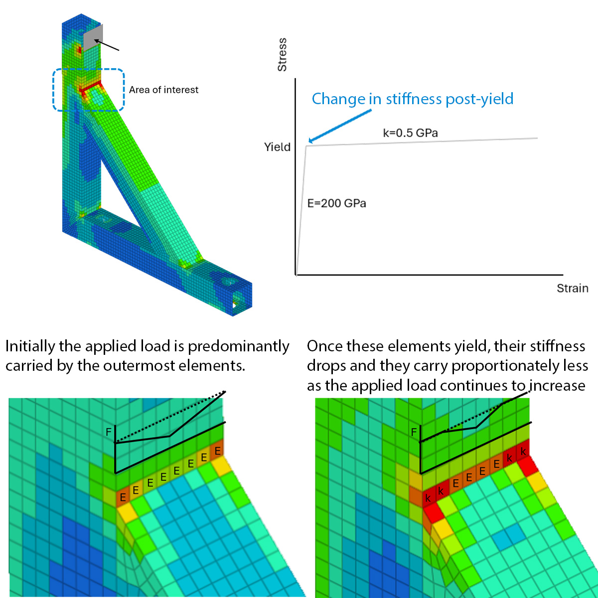 Bracket results illustrating the relationship between local response, load redistribution and load–deformation behaviour.
Why peak stress can be misleading
Consider a linear-elastic analysis of a steel bracket. As the applied load increases, the predicted stresses increase proportionally, even when the local von Mises stress exceeds the material's yield strength.
Once yielding occurs, however, the linear-elastic material model no longer represents the local post-yield response. The reported stress may therefore be useful for identifying regions requiring further assessment, but it should not automatically be interpreted as the physical stress within the yielded material.
A high local stress does not necessarily indicate immediate structural failure. Equally, dismissing a local stress concentration without considering material behaviour and the available load paths could lead to an unsafe conclusion.
The significance of the result depends on the material's ductility, the extent of the overstressed region, the loading conditions and the structure's ability to redistribute loading.
Plasticity and load redistribution
When a ductile material yields, its tangent stiffness generally decreases. As loading progresses, relatively stiffer regions of the structure may carry a greater proportion of any additional load.
For example, in a bracket subjected primarily to bending, local yielding can allow stresses to redistribute across the section. The structure may consequently sustain further loading beyond the point of initial yield.
This behaviour is not universal. A component loaded predominantly in direct tension may have fewer opportunities for redistribution, while brittle materials may fail with limited plastic deformation.
Non-linear material modelling can capture these changes in stiffness and load transfer, providing a more representative assessment of structural response beyond initial yielding.
Interpret plastic strain, not just stress
For non-linear material assessments, the maximum von Mises stress may not be the most informative result.
Consider an elastic, perfectly plastic material model. Once yielding occurs, the equivalent stress remains at the prescribed yield level, while plastic strain can continue to accumulate.
Consequently, inspecting the stress contour alone may conceal significant plastic deformation or the development of a failure mechanism.
Plastic strain distributions, load–displacement histories, permanent deformation and appropriate damage or failure criteria can provide a more meaningful basis for assessment.
The relevant outputs depend on the material model and the engineering acceptance criteria. Plastic strain does not, by itself, establish whether fracture has occurred.
Consider boundary conditions and local stress concentrations
Applied loads and constraints can introduce local stress concentrations that do not necessarily represent the behaviour of the physical structure.
Saint-Venant's principle helps explain why differences between statically equivalent loading arrangements may become less significant at locations sufficiently distant from their application.
This can allow simplified loading or constraint methods to provide useful results in regions remote from those idealisations.
However, when the region of interest is close to a connection, support or load introduction point, the local representation becomes much more important.
For example, the assessment of a loaded lug may require an appropriate contact model or the extraction of forces for comparison with established analytical methods and design criteria.
The analyst must determine whether a reported stress concentration represents a physical structural effect, a modelling idealisation or a numerical singularity.
Mesh convergence and results interpretation
Mesh refinement is an important method of assessing numerical sensitivity, but the result being examined must be relevant to the engineering objective.
Local peak stresses can be highly sensitive to element size, particularly near stress concentrations or mathematical singularities. In some cases, the reported maximum stress continues to increase with refinement without converging to a physically meaningful value.
Other quantities, such as global stiffness, reaction forces or load–displacement response, may exhibit different sensitivity to mesh resolution.
For non-linear analyses involving material damage or localised failure, mesh sensitivity can also affect the predicted failure response unless the modelling approach appropriately accounts for localisation.
The objective is therefore not simply to obtain convergence of the maximum reported stress, but to establish sufficient numerical resolution and confidence in the results governing the assessment.
Examine deformation, contact and energy histories
Stress contours are only one part of the available evidence.
Reviewing structural deformation can reveal unexpected load paths, unrealistic constraints, changing contact behaviour and potential failure mechanisms.
For transient dynamic analyses, the sequence of events is also important. Force, displacement, acceleration and energy histories help establish how loading is transferred and how the structure responds throughout the event.
Internal and kinetic energy histories, contact behaviour and artificial numerical energy contributions should be examined to assess whether the predicted response is consistent with the intended physics.
These checks are particularly relevant to explicit dynamics, where complex contact, large deformation and failure can evolve rapidly.
Verification and validation of results
Confidence in an engineering assessment depends on more than the apparent quality of the contour plots.
Numerical verification should establish that the model has been constructed appropriately, that the solution behaves as intended and that the results are sufficiently insensitive to relevant numerical choices.
Where suitable physical test data are available, comparison with measured behaviour provides additional evidence of the model's predictive capability.
Useful checks include:
- Applied loads, reaction forces and structural equilibrium
- Representative deformation and load-transfer behaviour
- Appropriate material models and failure criteria
- Mesh resolution and sensitivity of important results
- Contact behaviour and numerical stability
- Comparison with analytical calculations, physical testing or recognised benchmarks
The extent of verification and validation should be proportionate to the complexity of the analysis, the available evidence and the consequences of the engineering decision.
From numerical results to engineering conclusions
The value of FEA lies in translating numerical predictions into meaningful engineering evidence.
Experienced analysts consider the governing structural mechanics, material behaviour, modelling assumptions and limitations before drawing conclusions.
A reliable assessment should explain not only what the model predicts, but why the structure responds as it does, what confidence can be placed in those predictions and how the findings can inform subsequent engineering decisions.