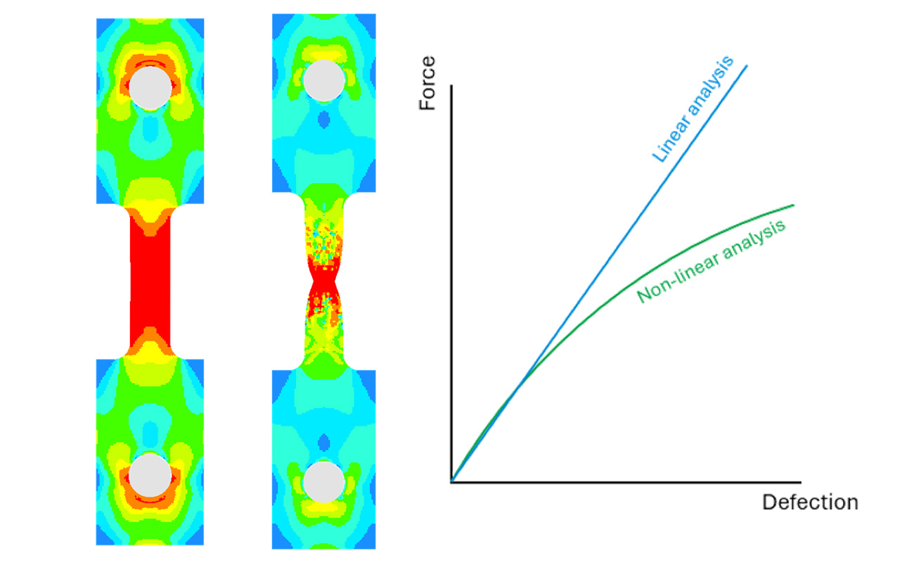
Linear structural FEA assumes that changes in loading produce proportional changes in stresses, strains and displacements, with the structural stiffness and boundary conditions unchanged. Many engineering problems depart from these assumptions as loading progresses.
Non-linear FEA allows changes in material behaviour, geometry and contact conditions to be represented, providing insight into how these mechanisms influence structural performance.
Three principal sources of non-linearity
Most structural non-linearities fall into three broad groups: material, geometric, and contact or boundary-condition non-linearity. A model can include one, two or all three, depending on the behaviour being investigated.
1. Material non-linearity
Material non-linearity occurs when the stress–strain response can no longer be adequately represented by constant linear-elastic stiffness. In metals, plasticity is a familiar example: yielding introduces permanent strain and allows stresses to redistribute as loading progresses. The subsequent response may include strain hardening, depending on the material model used.
Appropriate damage and failure models can extend the assessment to the initiation and progression of ductile failure, or brittle fracture, resulting in loss of load-carrying capacity.
Material non-linearity does not necessarily involve permanent deformation. Rubber and other elastomers can exhibit a non-linear but recoverable response, which can be represented using hyperelastic material models.
Linear-elastic results can support checks against yield or failure criteria, but they do not directly simulate the subsequent plastic deformation, damage evolution or associated load redistribution. The appropriate material model depends on the loading conditions and the structural behaviour the assessment needs to capture.
2. Geometric non-linearity
Geometric non-linearity becomes important when deformation changes a structure's stiffness, load paths or equilibrium conditions. A geometrically non-linear formulation accounts for the evolving configuration, capturing effects such as membrane stiffening, changing moment arms and structural instability.
A trampoline illustrates the principle. Its fabric has negligible bending stiffness and is held under tension. When a load is applied at its centre, the fabric deflects and changes shape. Its inclination allows membrane tension to develop vertical force components that resist the applied load.
As deflection increases, the geometry and membrane tension evolve, changing the effective stiffness and producing a non-linear load–displacement response. This illustrates an important distinction: geometric non-linearity can occur even when the material itself remains linearly elastic.
3. Contact and boundary-condition non-linearity
Contact introduces non-linearity when the conditions at an interface change during loading. Parts may begin separated, come into contact, transition between sticking and sliding, or separate again. These changes affect the forces transmitted between components and the stiffness of the assembly.
Similar behaviour can occur with gaps, one-way supports, fastener slip and joint clearance. Where these mechanisms influence structural performance, assuming permanently connected or unchanged interfaces may not adequately represent the response. Conversely, fixed or linearised interface conditions can remain appropriate where their assumptions are justified.
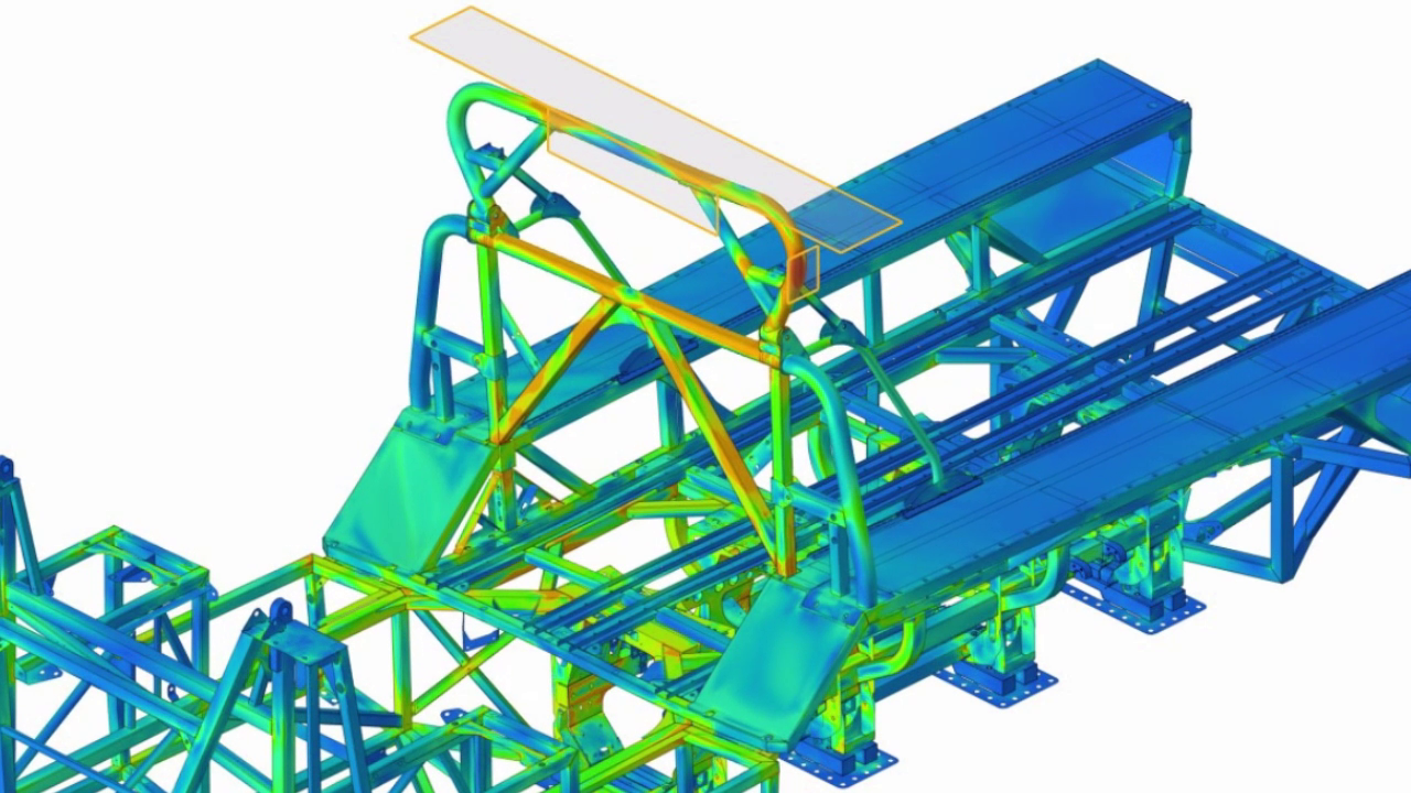 Non-linear finite element results for a vehicle rollover protective structure.
Why non-linear analysis can produce very different answers
In a linear assessment, a change in the applied loading produces a proportional change in the corresponding response. The model does not change its stiffness or load-transfer behaviour as the load increases.
A non-linear model can represent yielding, stiffening, softening, buckling and changing contact conditions. Applying twice the load therefore does not necessarily produce twice the displacement or stress. The distribution of load, and potentially the governing failure mechanism, may also change.
When to use non-linear analysis?
Non-linear analysis should be considered when changes in material behaviour, geometry or contact conditions could materially affect the engineering conclusions. The following provide useful indicators.
Material yielding and failure
When plastic deformation, stress redistribution, damage or fracture needs to be assessed, rather than simply checking linear-elastic stresses against an allowable limit. Non-linear material models are also required where the relevant stress–strain response is non-linear but recoverable, as with hyperelastic materials.
Significant deformation or rotation
When changes in geometry influence structural stiffness, load paths or stability. Geometric non-linearity can be important even at small material strains, particularly in structures undergoing large rotations, buckling or membrane action.
Changing contact conditions
When interfaces separate, re-establish contact, change contact area or transition between sticking and sliding, altering how loads are transferred through the structure.
Structural instability and load redistribution
When the assessment needs to follow buckling, post-buckling, progressive failure or collapse and the associated changes in load-carrying behaviour. A linear buckling assessment can provide an initial indication of instability, but it can produce non-conservative answers if imperfections are not considered and it does not describe the subsequent non-linear response.
When is linear analysis still appropriate?
Linear analysis remains an efficient and valuable approach when linear-elastic material behaviour, small-displacement assumptions and fixed or suitably linearised interface conditions adequately represent the response. It can provide a sound basis for strength, stiffness and design-comparison assessments within those limits.
The choice should be driven by the assessment objectives and the significance of the effects being simplified. Where changes in material behaviour, geometry or contact notably influence the result, the relevant non-linear effects need to be included.
Use linear analysis where its assumptions remain appropriate; introduce non-linearity where it changes the engineering conclusions.